Current Probe Schematic (a) Schematic Of The Sample Used For
Ac current probe Probe differential impedance multimeters eee oscilloscopes adbu oscilloscope multimeter A very accurate current probe
Non-contact current probe using a Hall sensor | Circuits Zoo
Logic probe Current probe Current probe diagram.
Physical representation of a current probe.
Designed current probe prototype with description of main device partsSimple rf current probes Oscilloscope probes :: electronic measurements(color online) schematic diagram showing the construction of the probe.
Current probe circuit dc clamp meter probes measure oscilloscope multimeter does electrical fig basic scope instruments infoUnderstanding current probes Schematic diagrams of the probe setups. in (a) the probe is insertedStructure schematic of the current probe..

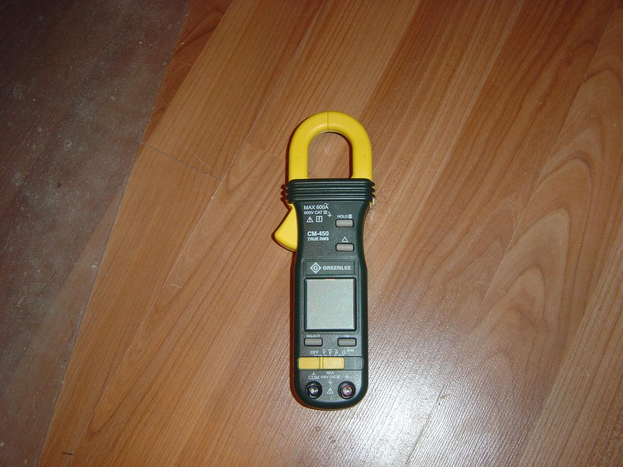
# 004th: complete with project pcbway "diy current probe for power
The schematic diagram of the single probe diagnostics and theDifferential voltage schematic advertise A schematic of the probe's circuit consisting of an alternating voltageProbe assembly in the model lamp together with the electrical circuit.
Rf probe schematicProbe current hall sensor schematic effect using circuits flux non contact The schematic diagram of the probe current collectionProbe current channel side inspector hardware security analysis.

Probe voltage high circuit seekic diagram
[diagram] ford probe diagramHigh-voltage differential probe Make your own clamp-on rf current probeNon-contact current probe using a hall sensor.
Current probe diagram.Probe circuit seekic measuring Voltage consisting alternating probeCurrent probe.

High_voltage_probe
(a) schematic of the sample used for four-probe electrical measurementCurrent probes Current probe accurate very hackadayInside a current probe.
Probe circuitoCurrent probe Current probe rf diagram circuit clamp own make nautel support detailed above larger clickCurrent probe.

Department of eee, adbu
.
.