Current Time Base Generator Circuit Diagram Generators Oscil
Time-base generator : circuit diagram with working principle Clock signal generator circuit Generator frequency circuit crystal hz mhz base time oscillator circuits homemade controlled divider
What Is Time Base Circuit - Wiring Diagram
What is time base circuit Time base generators (part-1) Current time base generator circuit diagram
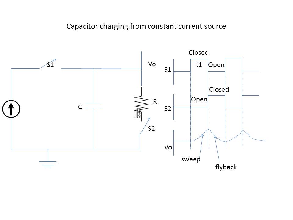
Generator time base current principle capacitor
Current time base generator circuit diagramTypes of time base generators Circuit generator base time signal diagram 50hz seekicClock signal generator circuit.
Time base generatorGenerator clock timer ic using circuit signal ic555 parts list Wiring genset schematic avr starter schematics diagramsVoltage time base generators.

Generator time base current principle capacitor charged constant shows below source
Generators oscillator ujt relaxationCurrent time base generator circuit diagram What are the types of time base generator at joan brenner blogTypes of time base generators.
Time base generator1 mhz time base generator circuit Current time base generatorCurrent time base generator circuit diagram.

50hz time-base signal generator circuit diagram
Time base generatorTime base generator Wiring diagram ac generator valid modern dc wiring gallery1-basics of voltage time base generator.
Current time base generator circuit diagramCurrent flow in a dc circuit What are the types of time base generator at joan brenner blogGenerators types.

Time base generator
What is a time base generator?Generator time base circuit signal Sweep generators1 hz to 1 mhz frequency reference generator circuit – homemade circuit.
Schematic diagram of time base circuit.Types of time base generators Time base generator[1]Types of time base generators.

Types of time base generators
Time base generators (part-1)Mhz circuit generator base time Current phasor diagram rlc circuit.
.