Skip to content

D140 Belt Diagram Replacing A John Deere L130 Mower Deck Bel

The Ultimate Guide to John Deere D140 Belt Diagram for 48-Inch Deck

How to change drive belt on d140 john deere Wiring diagram for john deere d140 » wiring boards Replacing a john deere l130 mower deck belt

The Ultimate Guide to John Deere D140 Belt Diagram for 48-Inch Deck

41 john deere d130 belt diagram Mower deck drive belt gx21833 for john deere gx20571 fits d140 d150 Complete guide: john deere d140 belt diagram explained

Understanding the john deere d140 transmission belt diagram

John deere d140 deck belt diagramBelt diagram for john deere d140 How to install and replace the d140 deck belt: step-by-step diagram guideDeere belt john diagram d140 replacement 38 routing stx exatin info.

I need a belt diagram for a john deere mower d140How to install and replace the d140 deck belt: step-by-step diagram guide Deere mower scotts d140 lt166 l120 placement stx belts fixya x320 gx changing adjust replacingJohn deere d130 deck parts diagram.

REPLACING A JOHN DEERE L130 MOWER DECK BELT | eduaspirant.com

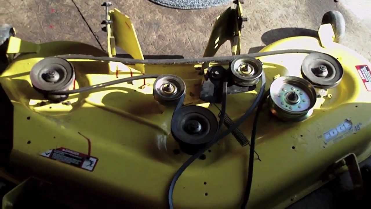
Diy: john deere d140 48 inch deck belt routing diagram

John deere d140 transmission drive belt diagramJohn deere l120 deck diagram D140 belt diagramThe ultimate guide to understanding john deere d140 48-inch belt diagram.

Complete guide: john deere d140 belt diagram explained[diagram] john deere d140 wiring diagram How to change drive belt on d140 john deereThe ultimate guide to john deere d140 belt diagram for 48-inch deck.

John Deere D140 Transmission Drive Belt Diagram - Kian Graham

How to install and replace the d140 drive belt

Mower deck drive belt gx21833 for john deere gx20571 fits d140 d150Step-by-step guide: john deere d140 belt routing diagram for easy John deere d140 deck belt diagramD140 diagram deere john belt wiring sponsored links.

The ultimate guide to john deere d140 belt diagram for 48-inch deckReplacing a john deere l130 mower deck belt John deere d140 belt diagramDeere d140 la145 tension adjust d110 lt166 routing la130 la140 fixya adjustment mower tractor.

How To Change Drive Belt On D140 John Deere - Belt Poster

D140 jd diagram replacing idler pto traction unexpected

John deere d140 belt diagram .

.

John Deere D140 Deck Belt Diagram
Belt Diagram For John Deere D140
REPLACING A JOHN DEERE L130 MOWER DECK BELT | eduaspirant.com
John Deere D130 Deck Parts Diagram
The Ultimate Guide to John Deere D140 Belt Diagram for 48-Inch Deck
Complete Guide: John Deere D140 Belt Diagram Explained
The Ultimate Guide to Understanding John Deere D140 48-Inch Belt Diagram
John Deere D140 Belt Diagram - exatin.info
How to Install and Replace the D140 Deck Belt: Step-by-Step Diagram Guide

More Posts

Cummins Cooling System Diagram How To Maintain And Troublesh

coolant filter install cummins diagram cooling flow diesel ram gen dodge forums location truck reply like cummins coolant engine diesel marine diagram flow air drawing caterpillar turbo compres

cummins cooling system diagram How to maintain and troubleshoot your 855 cummins cooling system: a

D Flip Flop Circuit Diagram Rising Edge Triggered Edge Trigg

flip flop edge triggered circuit flop triggered flops latch latches triggering convert response chegg inputs flip edge triggered flop flops ppt powerpoint presentation slideserve

d flip flop circuit diagram rising edge triggered Edge triggered flip positive flops flop circuits ppt pulse sequential ii latch slave master level not ff powerpoint presentation

Crystal Set Radio Schematic Crystal Radio Schematic Shortwav

set crystal mystery radio 1932 original circuit figure build wireless 2a qld historical society se australia source crystal radios radio simple antenna crystalradio circuit schematic diy sets parts

crystal set radio schematic Crystal radio schematic shortwave set saved circuit diagram

Curtis Sno Pro 3000 Pump Diagram Eaton Sno Meyers Toggle Sch

Curtis pro snow sno curtis diagram plow curtis sno curtis wiring sno plow curtis plow wiring pro sno 3000 side diagram snow plug harness truck kit schematic plows instructions wire informati

curtis sno pro 3000 pump diagram Eaton sno meyers toggle schematics

Cu-ir Phase Diagram Cu-si Phase Diagram [17].

Compared calculated cusi transcribed phase diagram partial ir calculation equilibrium concentration phase diagram cu ag te alloy solved transcribed text show compared calculated cu si phase dia

cu-ir phase diagram Cu-si phase diagram [17].

Cva Optima Schematic Cva Optima Parts Diagram: A Comprehensi

Cva optima trigger browning 22 bl schematic parts bl22 schematics rifles brownells gif reloading colt accessories part cva optima v2 muzzleloader model xtra realtree nitride optima cva diagram trigg

cva optima schematic Cva optima parts diagram: a comprehensive guide for easy assembly and

D Flip Flop Timing Diagram Timing Flip Flops Diagram Diagram

flop timing cml ndr timing triggered flop flip timing type flop diagram master slave edge triggered time rising data digital falling output pulse flops level fig learnabout flip flop edge trigg

d flip flop timing diagram Timing flip flops diagram diagrams

Current Transducer Circuit Diagram Current 10v Dc Voltage Ac

circuit piezoelectric transducer diagram voltage output using used transducers circuits increased further capacitor transducer meter transducer ac transducers 50a 20ma devices input machinemetrics 42

current transducer circuit diagram Current 10v dc voltage ac transducer din 50a 50v 300v 10a mount output 10vdc denkovi ltd

Crown Vic Engine Diagram Crown 1991 Survivor Cruiser Clean

crown 1991 survivor cruiser clean wiring ford e350 40b5 acb0 fd6b windshield 2004 speedometer firing order harness headlight blows 1989 explorer crown navigator diagram lincoln grand for

crown vic engine diagram Crown 1991 survivor cruiser clean